07 MRI
Pixel bandwidth
BW/pixel = (receiver BW) / N_read. Chemical-shift pixels = δf / (BW/px).
Listen
Listen · English
Simulation
Pixel bandwidth — Change the numbers; the scene follows.
Where it works
MRI scanner
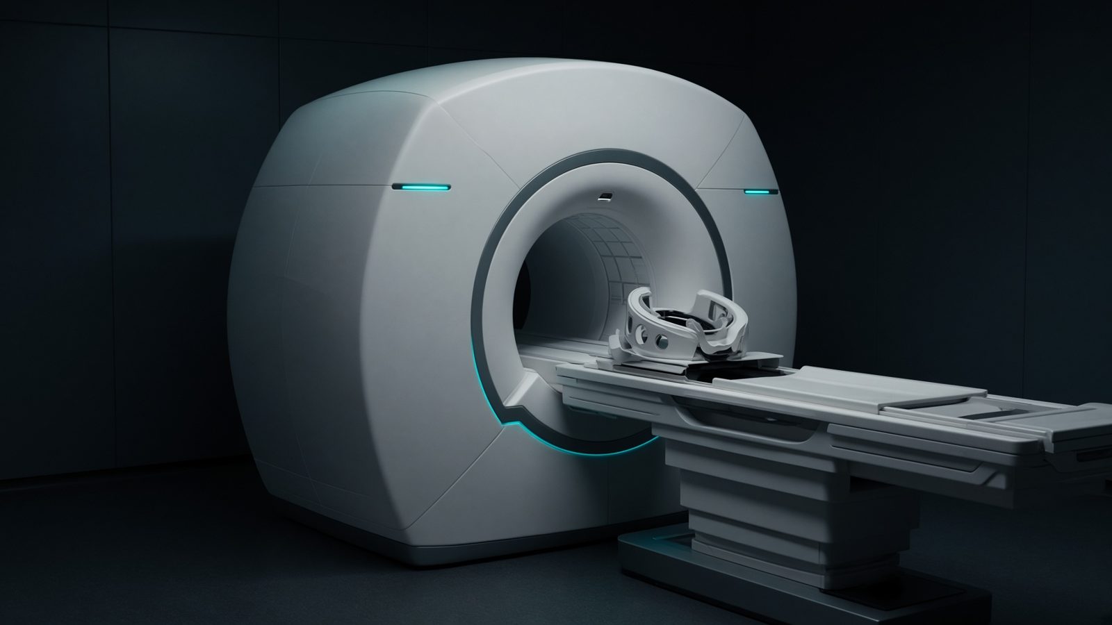
RF coil
At the RF coil — flip angle, SAR, SNR, receive bandwidth, and the pulse sequence.
Open this machineFormula
Variables
Results
BW/px
Pixel bandwidth
195.3125Hz/px
Δf
Frequency difference
223.5318Hz
n_cs
Chemical-shift pixels
1.1445px
Explanation
What it means
Receiver bandwidth is spread across the readout FOV. A 50 kHz BW on 256 samples is 195 Hz/pixel. Fat–water at 1.5 T is 220 Hz, so chemical shift is 220/195 ≈ 1.1 pixels; at 3 T it doubles unless you raise BW. High BW: less shift, less distortion, more noise (SNR ∝ 1/√BW). Low BW: prettier SNR, fatter shift, more metal distortion. This is a working relation in MRI physics.
Where it is used
Clinically it sits on the MRI scanner — RF coil. At the RF coil — flip angle, SAR, SNR, receive bandwidth, and the pulse sequence. MRI physics lives in the magnet, the gradient, and the voxel: Larmor, Ernst, diffusion, and SAR. These relations decide whether a sequence is possible, safe, and worth the time.
MRI scanner · Open this machineHow to use it
Enter receiver BW (kHz, ± as vendors differ — use the full width), readout samples, field strength and the ppm of the species (3.5 ppm fat–water). Read Hz/pixel and shift in pixels. Change one input and watch the curve and the simulation follow.
Symbols
- BWReceiver bandwidth50 kHz
- NReadout samples256
- B_0Field1.5 T
- δChemical shift3.5 ppm
Worked example
A typical case from the default values: BW = 50 kHz (Receiver bandwidth); N = 256 (Readout samples); B_0 = 1.5 T (Field); δ = 3.5 ppm (Chemical shift). Substituting into the relation gives BW/px = 195.3125 Hz/px; Δf = 223.5318 Hz; n_cs = 1.1445 px. These are teaching numbers — align them with your machine.
Typical values give
- BW/px = 195.3125Hz/px
- Δf = 223.5318Hz
- n_cs = 1.1445px
Where it comes from
The displayed formula is the working relation. BW/pixel = (receiver BW) / N_read. Chemical-shift pixels = δf / (BW/px). Usual reference: McRobbie / Bernstein. Derive it in the specialty lesson, then return here to pin the numbers.
Reference: McRobbie / Bernstein
Assumptions & limits
Some vendors quote ±BW (half). This calculator expects the full bandwidth that spans the FOV. Water–fat is 3.3–3.5 ppm; silicone is ~4.5 ppm from water.
Pitfalls
γ for ¹H is not γ for ¹³C. Ernst angle needs the true T1 at that field, not a 1.5 T table used at 3 T. SAR scales with B₀² and flip² — a 3 T copy of a 1.5 T protocol is not automatically legal. Some vendors quote ±BW (half). This calculator expects the full bandwidth that spans the FOV. Water–fat is 3.3–3.5 ppm; silicone is ~4.5 ppm from water.
Keep this
Name the nucleus and the field before you quote a Larmor frequency. Some vendors quote ±BW (half). This calculator expects the full bandwidth that spans the FOV. Water–fat is 3.3–3.5 ppm; silicone is ~4.5 ppm from water.
In this specialty