02 Imaging
HVL and attenuation
Compute μ, HVL, and transmitted intensity through thickness x.
Listen
Listen · English
Simulation
HVL and attenuation — Change the numbers; the scene follows.
Where it works
Radiography room
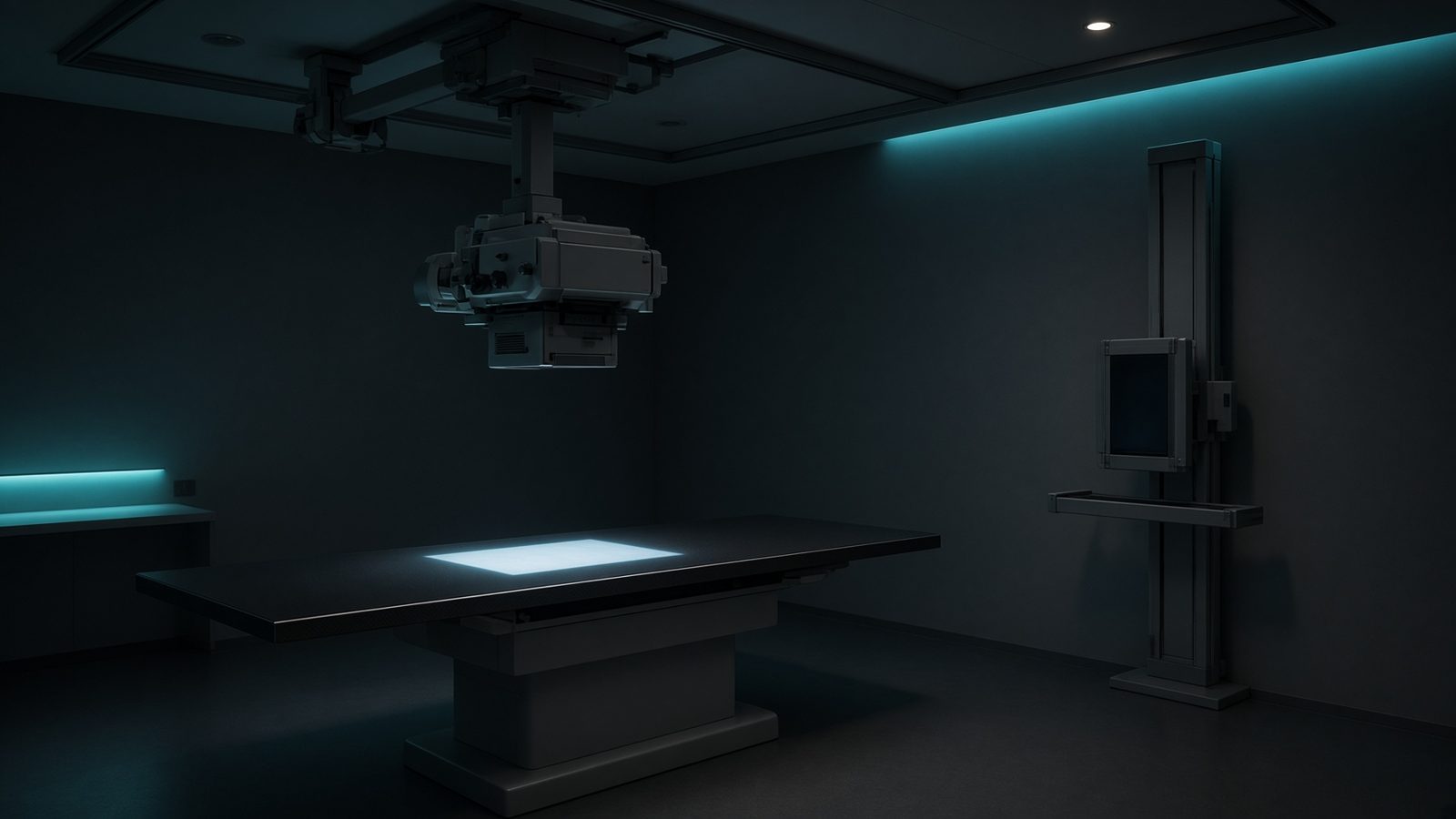
X-ray tube
At the focal spot in the tube housing — spectrum, output, SID geometry, and unsharpness start here.
Open this machineFormula
Variables
Results
I
Transmitted intensity
47.2367a.u.
I/I₀
Transmission
0.4724
HVL
Half-value layer
4.621cm
Curve
Explanation
What it means
Under narrow-beam geometry, intensity falls exponentially: I = I₀ e^{−μx}. The half-value layer ln2/μ is the thickness that halves the beam — a practical measure of quality (hardness) for kV x-ray beams. This is a working relation in Diagnostic imaging.
Where it is used
Clinically it sits on the Radiography room — X-ray tube. At the focal spot in the tube housing — spectrum, output, SID geometry, and unsharpness start here. Diagnostic equations live on the tube, the detector, and the patient: magnification, air kerma, CTDI, and why bone lights up at 70 kV. They turn a technique chart into physics you can defend.
Radiography room · Open this machineHow to use it
Diagnostic HVL is specified in mm Al (must exceed a regulatory minimum at each kVp). First HVL < second HVL because beams are polyenergetic (hardening). Change one input and watch the curve and the simulation follow.
Symbols
- I₀Incident intensity100 a.u.
- μLinear attenuation coeff.0.15 cm⁻¹
- xThickness5 cm
Worked example
A typical case from the default values: I₀ = 100 a.u. (Incident intensity); μ = 0.15 cm⁻¹ (Linear attenuation coeff.); x = 5 cm (Thickness). Substituting into the relation gives I = 47.2367 a.u.; I/I₀ = 0.4724; HVL = 4.621 cm. These are teaching numbers — align them with your machine.
Typical values give
- I = 47.2367a.u.
- I/I₀ = 0.4724
- HVL = 4.621cm
Where it comes from
The displayed formula is the working relation. Compute μ, HVL, and transmitted intensity through thickness x. Usual reference: Bushberg. Derive it in the specialty lesson, then return here to pin the numbers.
Reference: Bushberg
Assumptions & limits
Monoenergetic narrow-beam model. Broad-beam shielding needs buildup. For polyenergetic beams use an effective μ or tabulated HVLs.
Pitfalls
kVp is not the same as effective energy. CTDI is not patient dose — SSDE and organ dose come after. Do not quote DLP as if it were effective dose without a k-factor. Monoenergetic narrow-beam model. Broad-beam shielding needs buildup. For polyenergetic beams use an effective μ or tabulated HVLs.
Keep this
Technique is physics: kV sets contrast, mAs sets noise, filtration sets the spectrum. Monoenergetic narrow-beam model. Broad-beam shielding needs buildup. For polyenergetic beams use an effective μ or tabulated HVLs.
In this specialty