01 Therapy
Wedge factor and effective wedge angle
Physical WF = D_wedge / D_open. Dynamic/virtual: tan θ_eff = (MU_w / MU) tan θ_w.
Listen
Listen · English
Simulation
Wedge factor and effective wedge angle — Change the numbers; the scene follows.
Where it works
Linear accelerator
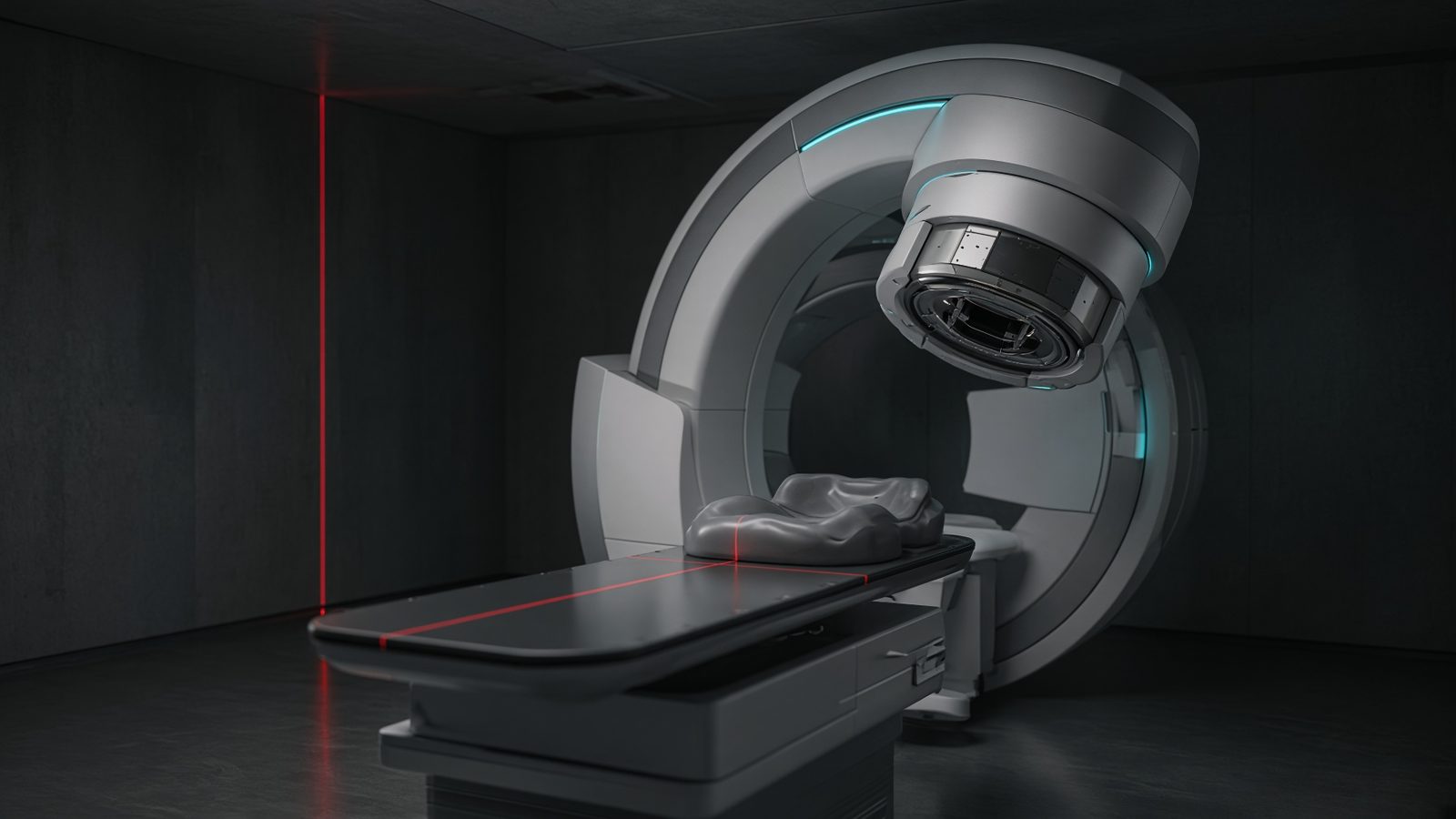
Treatment head
Inside the treatment head: monitor chambers measure output; wedges and leakage live here.
Open this machineFormula
Variables
Results
WF
Wedge factor
0.72
θ_eff
Effective wedge angle
34.715°
Explanation
What it means
A physical wedge attenuates more on one side, producing a tilted isodose. The wedge factor (central axis) is typically 0.5–0.8 depending on angle and energy, and it is an MU multiplier. A dynamic (virtual, flying) wedge mixes an open-field segment with a wedged segment; the effective angle follows the tangent rule. EDW / OmniWedge implementations differ in MU split but the tangent mixing rule is the teaching standard. This is a working relation in Radiotherapy.
Where it is used
Clinically it sits on the Linear accelerator — Treatment head. Inside the treatment head: monitor chambers measure output; wedges and leakage live here. Radiotherapy equations sit at the console and in the bunker: output, depth dose, equivalent square, and the monitor units that treat the patient. Hand-calc them beside the TPS, never instead of a commissioned plan.
Linear accelerator · Open this machineHow to use it
For a physical wedge enter D_w and D_open. For a virtual wedge enter the physical angle, total MU and wedged-segment MU. Read WF and θ_eff. Change one input and watch the curve and the simulation follow.
Symbols
- D_wWedged dose72 cGy
- D_openOpen dose100 cGy
- θ_wPhysical wedge angle60 °
- MU_wWedged-segment MU40
- MUTotal MU100
Worked example
A typical case from the default values: D_w = 72 cGy (Wedged dose); D_open = 100 cGy (Open dose); θ_w = 60 ° (Physical wedge angle); MU_w = 40 (Wedged-segment MU); MU = 100 (Total MU). Substituting into the relation gives WF = 0.72; θ_eff = 34.715 °. These are teaching numbers — align them with your machine.
Typical values give
- WF = 0.72
- θ_eff = 34.715°
Where it comes from
The displayed formula is the working relation. Physical WF = D_wedge / D_open. Dynamic/virtual: tan θ_eff = (MU_w / MU) tan θ_w. Usual reference: Khan / IEC 60976. Derive it in the specialty lesson, then return here to pin the numbers.
Reference: Khan / IEC 60976
Assumptions & limits
Central-axis WF only — off-axis the factor changes. Hot spots under the thin end and beam-hardening through a physical wedge are not modelled. Always use the measured WF table of the installed wedge.
Pitfalls
Never mix PDD from one SSD with TMR from another without converting. Field size at the surface is not the size at isocentre. A hand MU is a check, not a treatment. Central-axis WF only — off-axis the factor changes. Hot spots under the thin end and beam-hardening through a physical wedge are not modelled. Always use the measured WF table of the installed wedge.
Keep this
Name the SSD, energy, and field size with every PDD or TMR you quote. Central-axis WF only — off-axis the factor changes. Hot spots under the thin end and beam-hardening through a physical wedge are not modelled. Always use the measured WF table of the installed wedge.
In this specialty