06 Dose
Exponential attenuation
Narrow-beam transmission: I = I₀ e^{−(μ/ρ) ρ x}.
Listen
Listen · English
Simulation
Exponential attenuation — Change the numbers; the scene follows.
Where it works
Water phantom
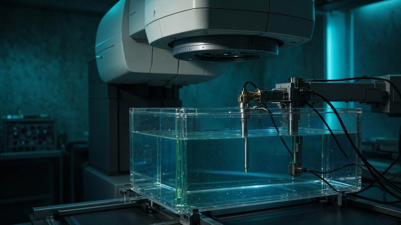
Ion chamber
In the water tank under the linac, at the ion chamber — reference dosimetry happens here.
Open this machineFormula
Variables
Results
I
Transmitted intensity
74.0818a.u.
I/I₀
Transmission
0.7408
HVL
Half-value layer
23.1049cm
Curve
Explanation
What it means
Narrow-beam attenuation uses the mass coefficient: I = I₀ exp[−(μ/ρ) ρ x]. μ/ρ comes from XCOM; multiply by density for μ. HVL = ln2 / μ. This is the same physics as the diagnostic HVL equation, written in mass form for any material. This is a working relation in Dosimetry.
Where it is used
Clinically it sits on the Water phantom — Ion chamber. In the water tank under the linac, at the ion chamber — reference dosimetry happens here. Dosimetry is the chamber in water under the linac, or the well counter in the hot lab: TG-51, TRS-398, kerma, and recombination. These numbers are the calibration the rest of the department borrows.
Water phantom · Open this machineHow to use it
Water μ/ρ ~ 0.03 cm²/g in the Compton plateau (0.2–2 MeV). Lead is huge at 100 keV (photoelectric) and still several cm²/g at 1 MeV. Use this for transmission through trays, couches and kV filters. Change one input and watch the curve and the simulation follow.
Symbols
- I₀Incident intensity100 a.u.
- μ/ρMass attenuation coeff.0.03 cm²/g
- ρDensity1 g/cm³
- xThickness10 cm
Worked example
A typical case from the default values: I₀ = 100 a.u. (Incident intensity); μ/ρ = 0.03 cm²/g (Mass attenuation coeff.); ρ = 1 g/cm³ (Density); x = 10 cm (Thickness). Substituting into the relation gives I = 74.0818 a.u.; I/I₀ = 0.7408; HVL = 23.1049 cm. These are teaching numbers — align them with your machine.
Typical values give
- I = 74.0818a.u.
- I/I₀ = 0.7408
- HVL = 23.1049cm
Where it comes from
The displayed formula is the working relation. Narrow-beam transmission: I = I₀ e^{−(μ/ρ) ρ x}. Usual reference: Attix / NIST XCOM. Derive it in the specialty lesson, then return here to pin the numbers.
Reference: Attix / NIST XCOM
Assumptions & limits
Good-geometry narrow beam. Buildup, scatter into the detector, and polyenergetic hardening are omitted. For shielding use NCRP TVLs.
Pitfalls
kQ is for that chamber and that beam quality — not a neighbour's value. Polarity and recombination are measured, not copied. A ⁶⁰Co N_D,w is not an MV calibration until kQ is applied. Good-geometry narrow beam. Buildup, scatter into the detector, and polyenergetic hardening are omitted. For shielding use NCRP TVLs.
Keep this
Trace every gray back to a protocol, a chamber, and a quality index. Good-geometry narrow beam. Buildup, scatter into the detector, and polyenergetic hardening are omitted. For shielding use NCRP TVLs.
In this specialty